Anwaar Amulet Starter Kit
The starter kit is a special collection of 3 boards. It was funded through crowdsupply in October 2025.
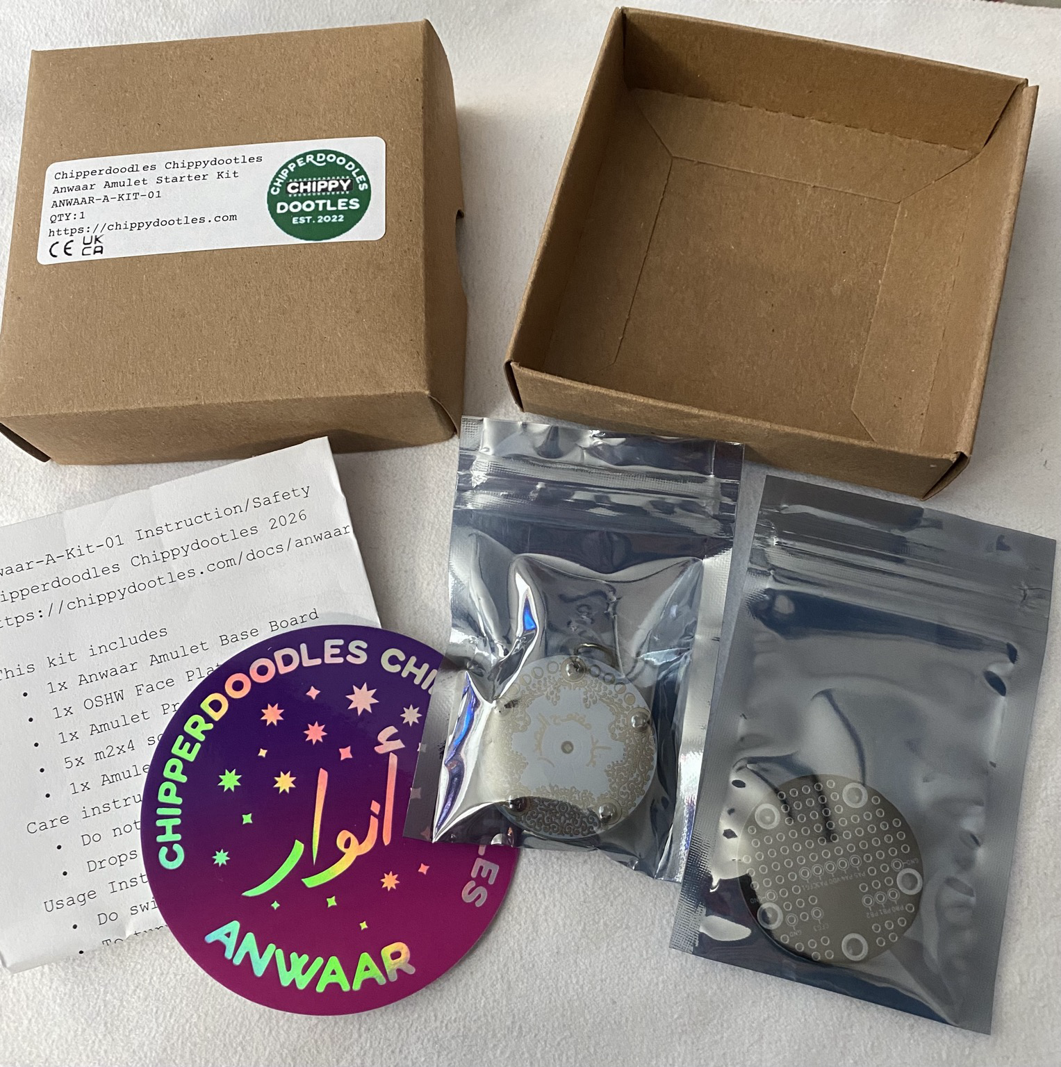
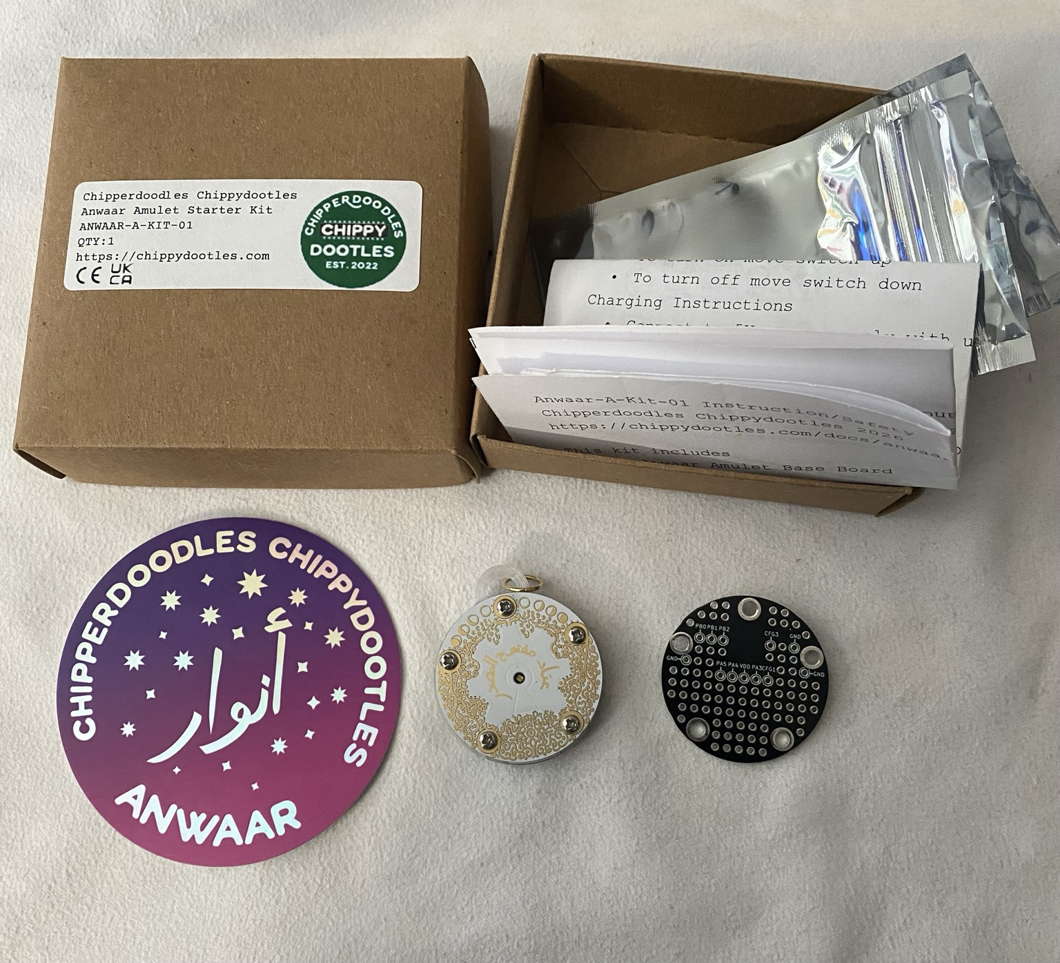
The Kit
contains:
- 1x A-TINY-15F base board
- 1x A-OSHW Face plate
- 1x A-PROTO Face plate
- 5x M2x4mm (top), 5x M2x3mm (bottom)
- 1x 3d printed spacer (petg)
- 1x cool sticker
- 1x insert
Base Board
For more information about the base board visit the page on the a-tiny-15f.
A-OSHW Face Plate
This face plate is a special design celebrating open source hardware. It uses the The modern standard arabic wikipedia page for open source hardware for the arabic that's on the gear. There's an analog RGB led and a capacitive touch pad. The board is assembled and fastened with this face plate and preprogrammed with the firmware in the case that someone just wants to wear or carry around a nice little board if they're not planning on making their own face plates and just wanted to support me <3.
Quick pin info:
- Voltage toggle (PA7): High 3.3v, Low 1.8V
- Red PB0, Green PB1, Blue PB2
- Touch: PIN PA5 (this is the keyhole pad)
Program Info:
The touch button cycles through 5 different modes, sinewave based beat cycle, sawtooth based beat cycle, hue++ cycle, single color pulse, and then sleep. It will loop to the start after the sleep. Sleep can be finicky to wake up back from. Sometimes I just hard reset by turning off and on if it's acting particularly troublesome.s
A-PROTO
This is a special prototyping face plate, it breaks out the header onto labled pads. It uses through hole pads to encourage prototyping but I ask you to be mindful that the hybird caps sits almost flush against the bottom side of the face plate, so don't use tht parts over the cap area unless you cut them to be < 1.6mm so they don't stab the cap and potentially short if they press through the hybrid caps shrink wrap. I thought about designing it with just SMD pads but the throughholes let you be much more flexible. You can also be creative like anu's use of crosstitching.
Charging
In a compromise for longer run time the amulet is set for a super full charge. Recommended usage is charge after depletion, remove from the charger after done and avoid frequent partial to full charges. Charge when already mostly full takes about 12 minutes, charge when depleted takes about 1hr 10mins. The schematic contains alternate resistor values if you want to change charging behaviour according to your usage. Expected usage for default settings is charge, unplug, run till depletion, repeat.
Fastening Screws
They kit contains 10 screws (already fastened). The screws are the same thread but 1mm different in length. The screws on the back (3mm length) act as extra security for the standoffs which are soldered to the base boards. In the unlikely event the solder connection is broken these screws will keep the standoffs fastened, this also helps agains the overtighting of the top face plate screws. The Top Screws (4mm length) help keep the face plate attatched and are recommend to used unless you are swapping plates, in the case of a drop these help lessen the impact on the solder connected headers, with out them it's more likely to damage the header connectors in a fall/drop situation. All screws are recommended hand tight snug.
Spacer
The spacer is 3d printed out of petg. I noticed a minor difference in height may make it hard for a face plate to stay connected without fastening screws but is a non issue once screws are fastened. Freecad files are provided of the boards and spacers if you want to make custom ones.
Programing
When powered on and plugged into the computer 2 different serial ports should enumerate. One of them is the programming port, the other is the serial debug port. It can be a toss up which one enumerates first, on my computer the programming port usually enumerates first but YMMV. If looking for a starting point check out the page on programming. There's also this if you use platformio (link is a wip). If you know what you're doing, the mcu is an ATTINY 1616, have fun!