The amulet family is a circular 36mm diameter design and the smallest of the Anwaar designs. Boards are planed to all share the following characteristics.
Currently there are two official base boards, the A-TINY-15F, and the A-TINY-20F
A-TINY-15F is certified open source hardware!!
We're also on crowd supply!! Please subscribe to stay in the loop for when we go live!

Download: Original size PDF of pinout
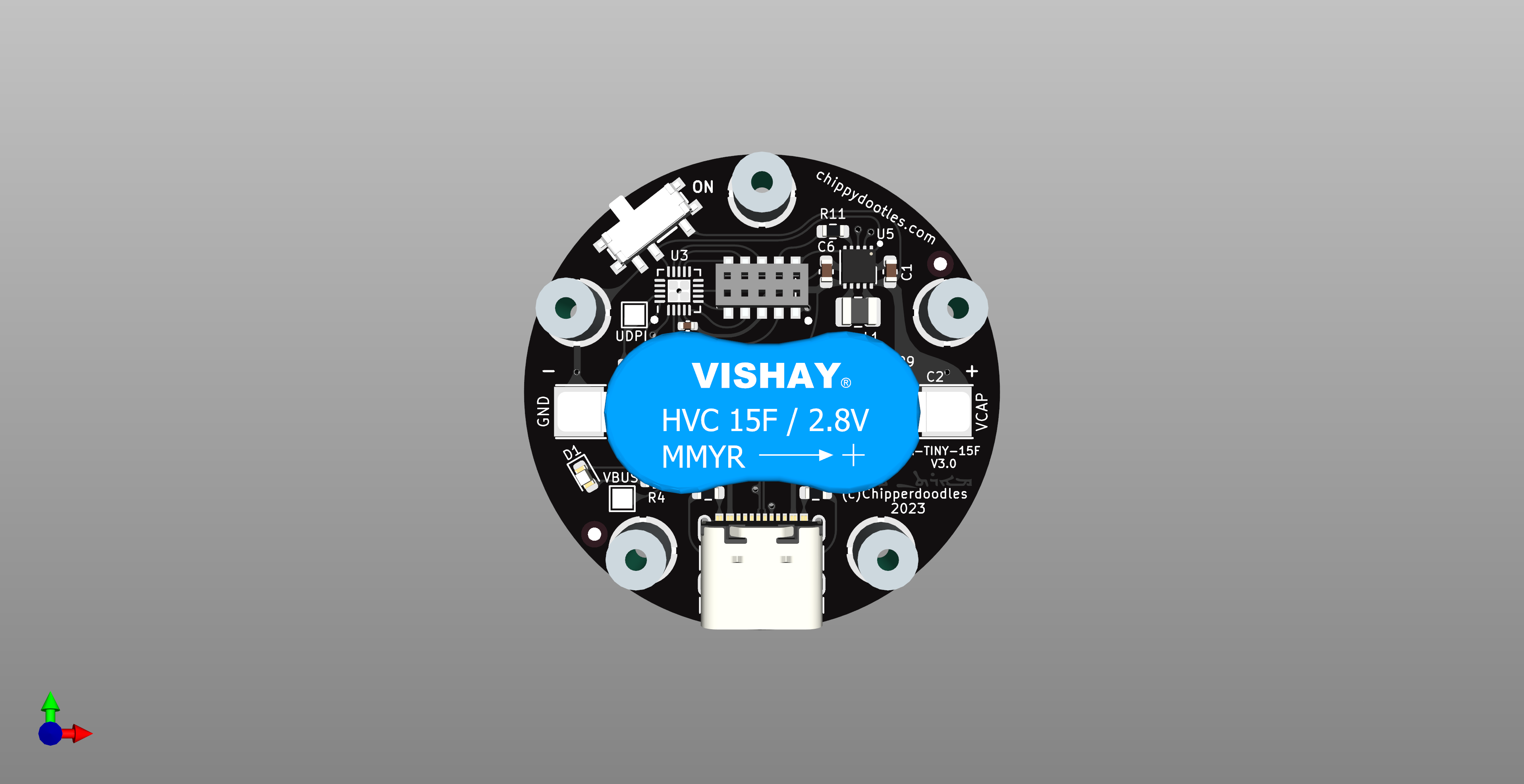
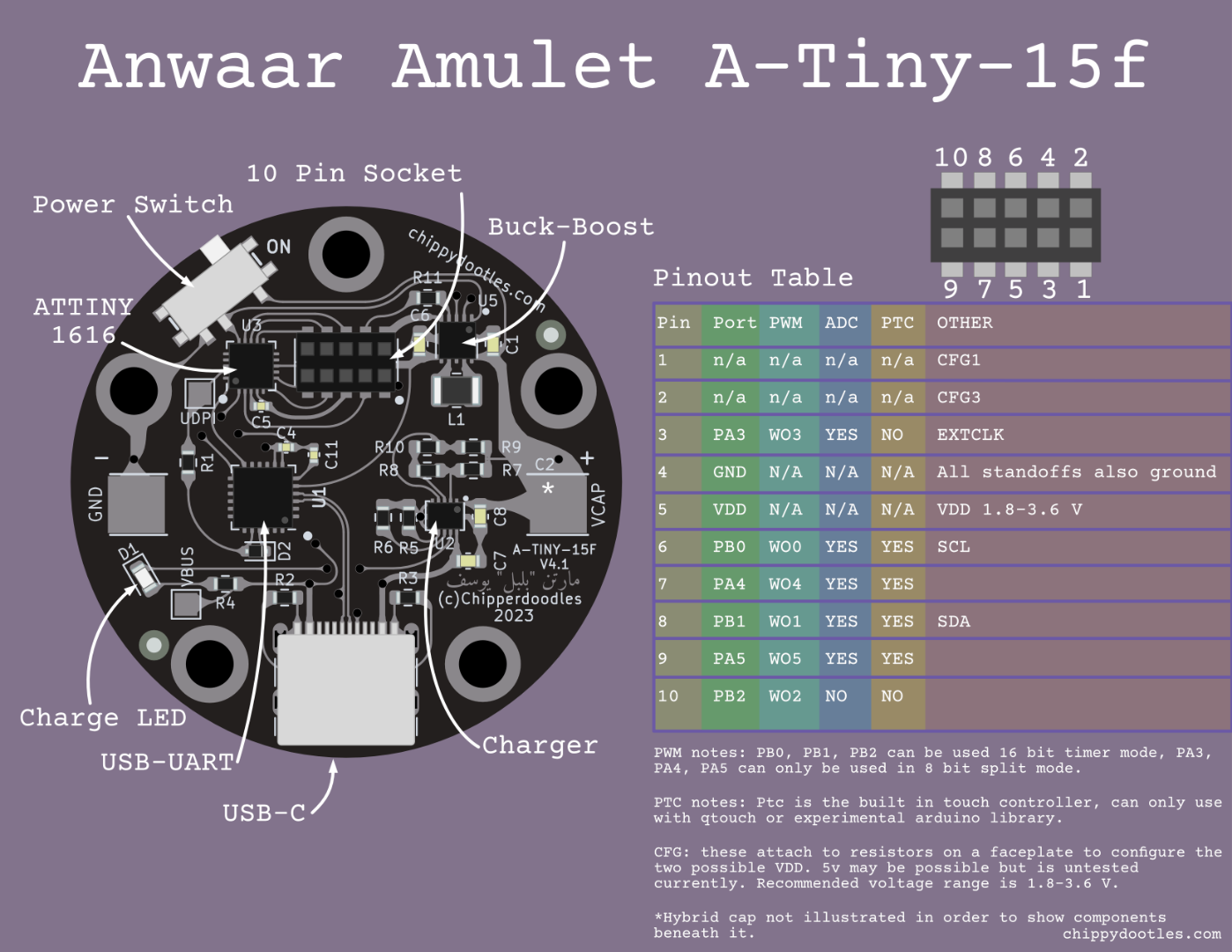
Pinout for A-Tiny-15F 3.0
| Pin | Port | PWM[^1] | Analog[^2] | PTC[^3] | Other |
|---|---|---|---|---|---|
| pin 1 | N/A | N/A | N/A | N/A | CFG1[^4] |
| pin 2 | N/A | N/A | N/A | N/A | CFG3[^4] |
| pin 3 | PA3 | WO_3 | AIN3 | NO | ExtCLK |
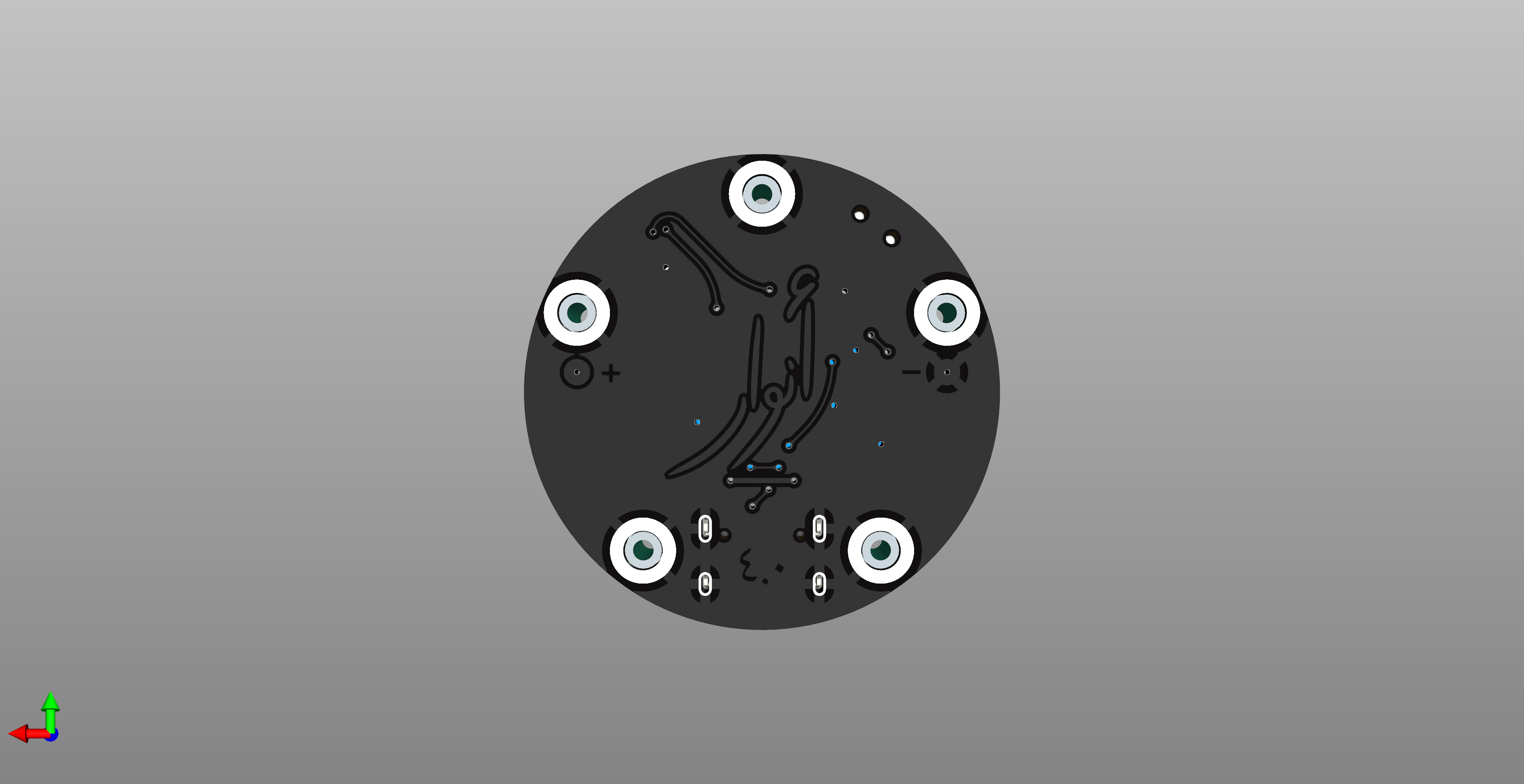
| pin 4 | GND | N/A | N/A | N/A | All Standoffs are GND |
| pin 5 | VDD | N/A | N/A | N/A | Voltage depends on R-CFG |
| pin 6 | PB0 | WO_0 | AIN11 | X5/Y5 | SCL |
| pin 7 | PA4 | WO_4 | AIN4 | X0/Y0 | |
| pin 8 | PB1 | WO_1 | AIN10 | X4/Y4 | SDA |
| pin 9 | PA5 | WO_5 | AIN5 | X1/Y1 | |
| pin 10 | PB2 | WO_2 | NO | NO |
Internal Pins: Pin PC0: connected to VEN. This can be used with ADC to check cap voltage when amulet switched on. It is disconnected from Vcap when amulet is switched off. PIN PA7: Connected to VSEL of buck-boost. Pulling this pin high Selects Voltage 1, pulling this pin low selects Voltage 2.
Footnotes:
- 1: TCA0[^1]
- 2: ADC0[^2]
- 3: Peripheral touch controller[^3]
- 4: Connected to CFG1 and CFG3 on TPS63900 buck-boost regulator[^4]
The MCU on board is the ATTINY 1616. This is a very small 8-Bit AVR chip that can do a lot. These chips are very easy to work with and have decently low active power (when clocked accordingly). Thanks to a community made arduino core these are very easy to get programmed and started with.
It has a Touch Peripheral which allows for some fun designs however the caveat is that it relies on Microchips closed source (but free to use) Qtouch libraries. There is an experimental arduino library reverse engineered in progress so ptc may be possible in arduino!
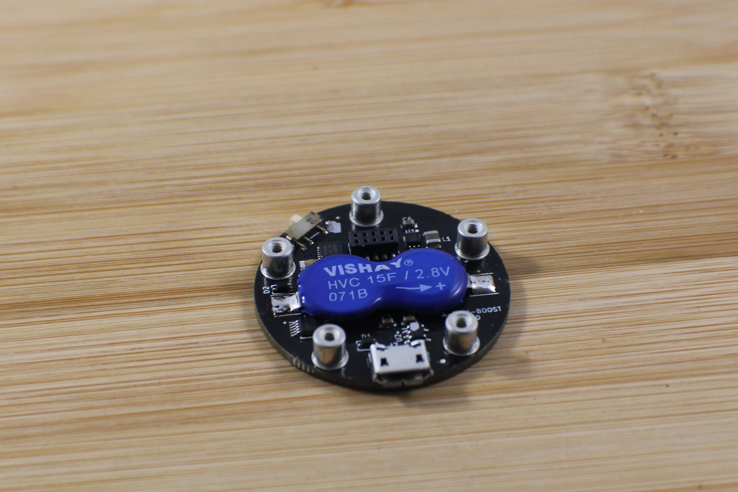
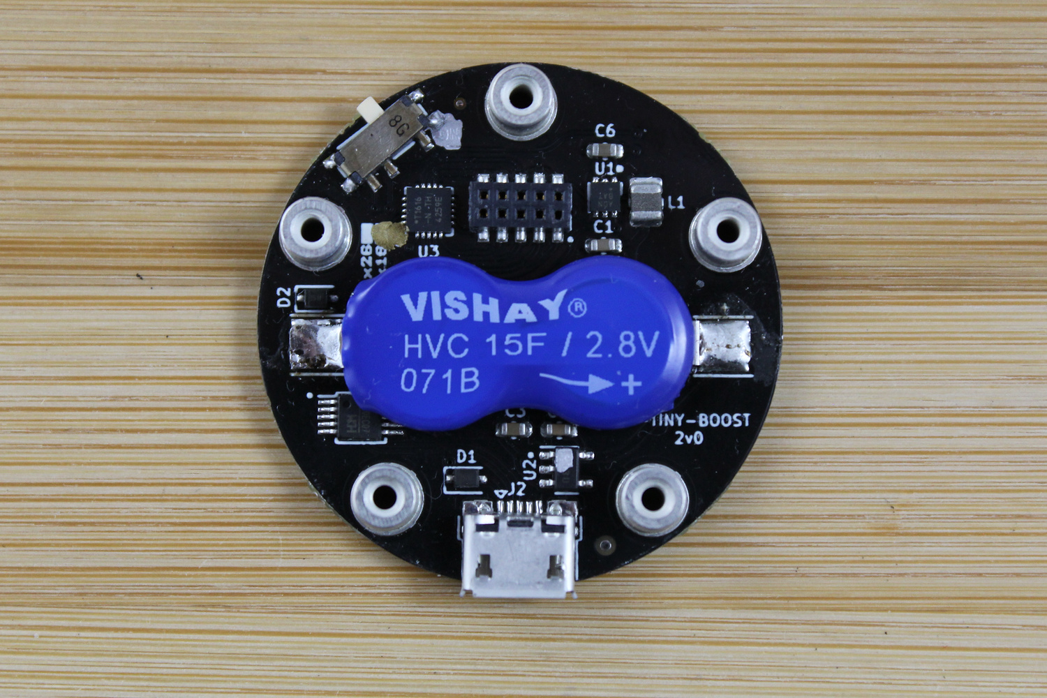
The energy storage is a 15 Farad Hybrid cap. As per the data sheet and application notes I limit CC charging to ~20mA and cut charging off when current reaches 5mA. Max discharge of the caps can be done safely up to 70mA however for long running times I advise average currents to be kept < 2mA. I've had pwm animated leds run from 6-8 hours depending on average current draw.
The TPS63900 is a new buck-boost converter from TI. It can output 1.8-5.0V and supports input current limiting as well as toggling between 2 different output voltages. On this base board the input current is limited to 50mA max to help protect the hybrid cap. Due to the way the resistor configuration works this leaves us with configurable output voltages of 1.8-3.6V possible. In concept, Toggling voltages is to switch to a lower voltage when the chip is sleeping or doesn't need a high voltage for leds or transmit power. The ATTINY has a wide vin so you can shave some power usage by switching to 1.8V while sleeping. If you do use capability this keep in mind the max/min voltage of any peripheral ICs/Sensors you may have in your face plate design.
Voltage selection is attached to pin PA7 on the mcu. Pull High for V-CFG1 and pull Low for V-CFG3.
Charging is done over USB connector.
Version 1.0 Have a micro USB Connector. And charge with a simple LDO with a fixed voltage of ~2.8V. This was a simple and cheap way to charge however lacked indication of charge state.
Version 2.1+ Have a USB Type C connector. They use a Rohm CC/CV charging IC. I was lucky to come across this as it gave me the ability to set charge voltage, charge current and cut off current as well as have a Status led. Most charge controllers are made for very specific battery chemistries so having something as configurable as this was nice.
you can effectively ignore versions 1.0-2.1 as they were unreleased
The A-TINY-20F is a drop in replacement for the A-TINY-15F, Only the charging and energy storage subsystem are different. The rest is the same.
| Pin | Port | PWM[^1] | Analog[^2] | PTC[^3] | Other |
|---|---|---|---|---|---|
| pin 1 | N/A | N/A | N/A | N/A | CFG1[^4] |
| pin 2 | N/A | N/A | N/A | N/A | CFG3[^4] |
| pin 3 | PA3 | WO_3 | AIN3 | NO | ExtCLK |
| pin 4 | GND | N/A | N/A | N/A | All Standoffs are GND |
| pin 5 | VDD | N/A | N/A | N/A | Voltage depends on R-CFG |
| pin 6 | PB0 | WO_0 | AIN11 | X5/Y5 | SCL |
| pin 7 | PA4 | WO_4 | AIN4 | X0/Y0 | |
| pin 8 | PB1 | WO_1 | AIN10 | X4/Y4 | SDA |
| pin 9 | PA5 | WO_5 | AIN5 | X1/Y1 | |
| pin 10 | PB2 | WO_2 | NO | NO |
Internal Pins: Pin PC0: Pin has been disconnected in this version of the board to keep safer. PIN PA7: Connected to VSEL of buck-boost. Pulling this pin high Selects Voltage 1, pulling this pin low selects Voltage 2.
Footnotes:
- 1: TCA0[^1]
- 2: ADC0[^2]
- 3: Peripheral touch controller[^3]
- 4: Connected to CFG1 and CFG3 on TPS63900 buck-boost regulator[^4]
same as the 15F version
The energy storage is a 20 farad Lithium ion hybrid capacitor. As per the data sheet and application notes I limit CC charging to ~80mA. Continuous current is rated for 80mA however for long running times I advise average currents to be kept low. I've had pwm animated leds run from 6-8 hours depending on average current draw.
Same as the 15F version
Charging is done over USB connector. Same Type C connector. These use a TI CC/CV charging IC. This is meant for Li+ and LiFePo4 batteries but works for this hybrid cap. Charging voltage is set 4.05, discharge cutoff is set for 3.0v It is safe to discharge these caps to 2.5V but the IC ties it's cutoff with the charge voltage.